Command Activation
| Ctrl + m |
Measure→Auto Features→Line Generator |
|
| Keyboard |
Main Menu |
Toolbar |
Definition
The Line Generator feature
builds and tolerances 2D line features. This allows building of
offline features when not connected to a coordinate measuring machine or
when the
production part is not available. The Line Generator also provides tools
to build all motion path that can be executed on demand for the measuring of the new
line.
The Line Generator provides complete access to define
a line feature. The tool
has two functions, its primary function is to create new features, it also provides
access to editing an existing feature whether created by the generator or
manually taught.
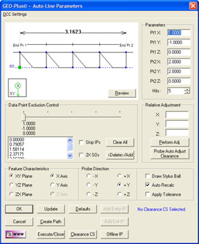 |
| figure 1,
The Line Generator |
Using the Line Generator to Create a New Feature
To create a new feature, activate the generator and
follow these steps:
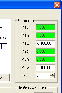
Step 1 - Defining the End Points and Hit Count
Complete the selections in the Parameters
Group
- Enter the XYZ PCS Values for End Points 1 and 2.
- Select the number of hits required.
Step 2 - Feature Characteristics
Complete the values required in the Feature
Characteristics Group
- Select the projection plane, XY, YZ or ZX.
- Select the reported PCS Pierce Axis.
Step 3 - Probe Direction
In the Probe Direction Group, select the appropriate
probing direction.
Step 4 - Motion Path Adjustments
There are several tools available to build motion
paths to ensure clear motion without collision into the inspection part, clamps and other obstacles. These include Clearance Coordinate Systems,
offline IPs and Automatic IPs.
Clearance Coordinate Systems
A complete description on Clearance Coordinate Systems
can be found here.
Creating offline IPs and Automatic IPs
Once the Clearance Coordinate System has been
establish and set active, Offline IPs can be generated to build a motion
path for safe CMM travel,
see Offline IPs.
Special Interim Point Commands
In most applications, the use of the command <Add
Entry IP> and <Add Exit IP> will ensure safe transition for your CMM. The use
of these commands requires that a
Clearance CS is
currently set active.
The Add Entry IP command calculates an IP directly over
the feature in the normal base plane. For example, in the XY line example,
the first Standoff Point is extracted and projected into the XY Base plane
of the active Clearance CS. The motion will start directly over the line and
plunge to the first SO safely.
The Add Exit IP command creates a similar IP to Add
Entry IP except it will use the last SO.
The combination of these two
commands instructs the CMM to safely position itself directly over the first
and last SO respectively within the current Clearance CS base plane.
The Entry IP will position the CMM directly over the first SO and commence the motion required for the measurement
by moving directly to the first SO.
All motion will be executed until the last SO is reached. Finally, motion will exit
the feature by a direct line from the last SO into the
Clearance CS base plane safely.
In most applications, this sequence of events will be sufficient for safe
CMM travel.
Execute
This command acts upon the parameters entered in the
Line Generator and instructs the CMM to perform the inspection under motion.
Ok
While the <Execute> button performs the measurement on
demand, the <Ok> command will process the feature record and append it to
the current inspection. The <Ok> command is used when in a offline mode,
editing an existing feature or building the inspection report without the
need for immediate feedback.
Relative Adjustment
The Relative Adjustment command will offset the
current XYZ end points a specified distance. This is helpful when measuring
similar features. An example would be a series of five +Y Lines 1.00" apart in the
+Y direction. Build and Execute the first line using the
Line Generator. When the feature has been completed, activating the Line
Generator will display the last known values, or in this case, the parameters
of line number one. Enter
0.0, 1.0, 0.0 in the Relative Adjustment group and press <Perform Adj>, the
line XYZ end points will update. If you are using Entry and Exit IPs, they
will update automatically. Press the Execute command and the CMM will transition and measure
line
number two.
Review
This command is useful when learning to use the Line
Generator. As shown in figure 2, the Review command displays the current
settings and highlights any potential problems. Here we see a highlight
(***CAUTION***) indicating there are no Entry or Exit IPs in the motion
path.
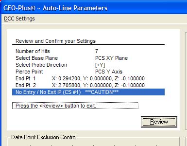 |
| figure 2,
The Line Generator Review |
The motion path does not show a clear path into the
line and out of the line. You have to choose if this is acceptable based
on your part. To return to the graphic display, press the <Review>
button
again.
Probe Auto Adjust Clearance
The line end points will determine the full range of
CMM motion. The CMM will move from end point 1 toward end point 2
inclusively. It is not always possible to locate safe end points that
provides proper clearance for the current stylus during CMM motion. To
illustrate, refer to figure 3, we have a production part with known end
points at:
| End Point 1: |
X=4.500" |
Y=1.000" |
| End Point 2: |
X=3.500" |
Y=2.250" |
| Probe Depth: |
Z=-0.100" |
|
 |
| figure 3,
End Point
Example |
Enter the end point XYZ values in the Parameters
Group. To allow for the size of the current stylus we will need to move the
end points toward the center of the defined line. This ensures the stylus
contacts the line away from the blended corners or other obstacles.
In figure 4, we have entered the nominal line end
points as defined in the drawing. Processing the command <Probe Auto Adjust
Clearance> will calculate new end points, moving them toward the center,
see figure 5. The distance the end points are moved equals 200% of the
current stylus radius. The stylus diameter used for this example is 0.100".
Here we show the new end points:
| End Point 1: |
X=4.4375" |
Y=1.078125" |
| End Point 2: |
X=3.5625" |
Y=2.171875" |
| Probe Depth: |
Z=-0.100" |
|
 |
 |
| figure 4, Before End Point Adjustment |
figure 5, After End Point Adjustment |
Data Point Exclusion Control
Not all lines being measured are continuous between
the endpoints. The line may have slots or other voids that will require the
data points to be adjusted to prevent a bad data point being introduced into
the line calculation.
 |
| figure 6,
Data Point Exclusion Control |
Removing data points from the final motion path can be
accomplished with the Data Point Exclusion Control. As shown in figure 6, we
have removed the data point at position number three.
The graphic display of the line contains four
components for the line being generated. Starting at the top of the graphic,
there is a vector length shown of 2.411600". This is the total length of the
line between the end points. The next component below, shows the line
between the end points displaying the data point contact locations. The
third component displays the direction and expected motion path. The last
component shown in the lower left refers to the PCS projection plane (XY)
and the PCS Pierce Axis (Y) used for reporting.
To use this exclusion control, start by identifying
the data point you will remove from the motion path. The slider control,
when moved, displays the XYZ coordinates for that contact point. In the
graphics, a small green square will follow the slider as you move it to
identify the data point being selected. There is also a list located below
the slider that lists the data point by the vector distance from end point
one.
To exclude a data point, slide to the data point and
press the button <Delete>/Add. When deleted, the graphic will show a
continuous path over the previous site of the data point. The list will add
the text "(removed)" behind the listing for that data point. The
<Delete>/Add button is a toggle which will replace a data point that has
been removed.
A second method of toggling the state of a data point
involves the use of the list control. Highlight the data point and double
left-click which will toggle its state.
NOTE: You can change the number of data points
required for the line while data points have been removed. By changing the
number of hits, you will slide the data points along the line to correspond
to the changed number of data points.
2X SOs
This check option exaggerates the distance of the
stand off distances in the graphic display. The Line Generator graphics
scales the relationship of the line and its motion path. If the line is
large, or the stand off distance is small the graphic displays the motion
path too close and becomes hard to distinguish. Select this option by
checking which will double the standoff distance only for displaying.
|