|
Command Activation
| m |
Measure→Line |
 |
| Keyboard |
Main Menu |
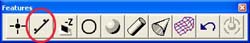
Toolbar |
Definition
A line is the trail left by a point which moves in a constant direction. Lines are
infinitely long and have no width. A line is characterized by a point somewhere along its
length and a direction. In Geomet a line is characterized by a PCS base plane pierce point
and two or three base plane projection angles. Its reported location is the point where
the line intersect with a PCS axis.
The Line feature provides you with the means to measure multi-point 2D Lines. 2D lines
are projected into a PCS base plane and report the angular deviation in the current PCS
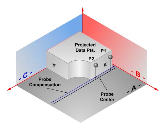
base plane and a 1D pierce value of a PCS base axes, see figure 1. The line feature is
multi-point consisting of 2 - 32767 data points.
 |
|
figure 1, Line projection into PCS |
In figure 1, we captured 2 -X data points which are projected into the XY PCS
base plane. The line is solved based on the center point values. Then the probe
compensation is applied to arrive at the final line solution. The line intersects the X
axis of the PCS and its location is reported as an X value.
Measure a Line
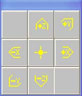
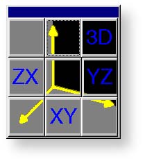
When starting the line tool < m >, you will be presented with a direction selector
dialog if Auto-Direction is turned off. The direction selection allows you to choose the
probing direction suited for the line to be measured, see figure 2.
 |
 |
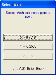 |
figure 2,
Direction Selector |
figure 3,
Projection Plane |
figure 4,
Axis Intersect |
After you select the probing direction, Geomet will prompt you to "Measure a -X
Line". Should Auto-Direction be turned on, Geomet will display "Measure a
Auto-Line". Proceed to capture the required number of data points.
The determination of the PCS base plane is supplied by the operator after the capturing
of the data points, see figure 3. Depending on the angle of the line, Geomet will
prompt for the selection of a PCS axis to report, see figure 4. Geomet uses an
angle of ± 10° between the line normal to a PCS axis to determine if the operator should
be prompted to select the pierce axis.
For example, if a line being measured crosses the PCS X axis at 1.000" and has a
reported angle of 85°, the operator will not be prompted to select a PCS axis. Should the
same line have a reported angle of 75°, then Geomet would prompt the operator to select
the pierce axis showing the solutions of both values as shown in figure 4.
After completing the first measured line, Geomet auto-cycles preparing to measure
another line. Note: after the first measure line is completed, Geomet will not prompt you
for a projection plane. It is assumed that you will continue measuring lines in the
original selected plane. Should you require a new projection plane, press
< Esc > and
select the line tool again.
The direction of the line is determined by the direction of the data points, from the
first data point to the second. In figure 1, the order the data points were captured
created a reported angle of -90° whereas should the order have been reversed, the
reported angle would be +90°. NOTE: see
Switching the Reported Angle Directions
below. This is important when applying a tolerance value to the angular component.
For all Multi-Point Line features. The default number of points used for measurement is
controlled by the value in System
Options. Therefore when you press the default line measurement tool < m > Geomet
responds to measure a line with the default number of data points. Should you require to
measure a line with a number of data points other than the default, press the
< shift + M > keys on the keyboard. Geomet will then prompt you for the number
of data points, see figure 5.
 |
|
figure 5, Enter number of hits required |
During the capturing of the data points, should you want to change the requested
number of data points you can press the line key repeatedly and the count will increase by
one with every depress without losing data points already captured.
If you have already captured sufficient data points to satisfy the line press
< F5 >, Terminate, to solve the line without having to capture the remaining prompted
data points.
Tolerance
Tolerance of Lines is available in Cartesian / Linear
format.
Switching the Reported Axis
 |
|
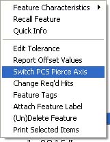
figure 6,
Switch PCS Pierce Axis |
To switch the reported pierce axis of a already measured or constructed line, highlight
the line in the report area and right-click. A sub menu will appear where you can choose
[Switch PCS Pierce Axis], see figure 6.
The option is available only when the line has not been used as a PCS component and
does not have a
reference lock
attached to it.
As mentioned previously, the order the data points were taken in will configure which
angle will be reported. If you want to switch the supplement angle with the normal
reported angle, there exists a option flag that can be set.
 |
|
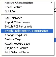
figure 7, Switch Angles |
To switch the angles, highlight the line feature in the report section by
left-clicking on it. Once the feature is highlighted, right-click to bring up the sub-menu
as shown in figure 7. Choose "Switch Angles....". The report will update and
reflect the switch ahs been applied. To change it back, toggle the switch again by
selecting "Switch Angles...." again.
|