A cylinder is the trail left a line which revolves around and at a constant distance
away from a parallel line called its axis. A cylinder is characterized by a point on its
axis, the direction of its axis and by its diameter or radius.
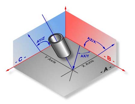
The cylinder feature determines the diameter, PCS pierce point and attitude of the axis
of bores and bosses. The attitude of a cylinder axis is expressed like the attitude of the
normal of a plane, using the characteristic identifiers AX/Y, AY/Z and AZ/X, see figure
4.6b. These angles can vary between 0° and ± 180°. The axis of a cylinder has a
direction as well as an attitude: its direction is from a group of points measured near
its bottom toward a group of point measured nears its top.
The reporting of the position in the PCS is the point where the axis of the cylinder
intersects a PCS base plane, called its pierce point. Geomet determines which PCS base
plane to report by determining which PCS base plane the axis of the cylinder is most
normal too, see figure 1.
 |
| figure 1, Cylinder Projection |
To measure bores or bosses press the Cylinder key <c> for an
6 point (or the default as established in System Options) cylinder, or
<shift + C > for
a multi-point cylinder, see figure 2.
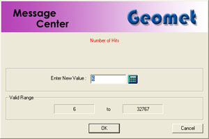 |
| figure 2, Multi-Pt Entry |
If Auto-Direction is not enabled, Geomet will prompt you for the type of cylinder
as shown in figure 3.
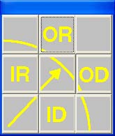 |
figure 3,
Select Characteristic |
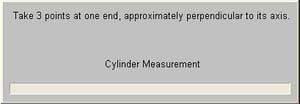 |
| figure 4, Collect First 3 Points |
|
 |
| figure 5, Collect Last 3 Points |
Collect the first 3 data points at or near the "bottom" of the bore or
boss, see figure 4. Collect the last 3 data points at or near the
"top", see figure 5. Should you require more than 6 data points, the
data points after 3 and less than total data points - 3 can be captured between the
"bottom" and "top".
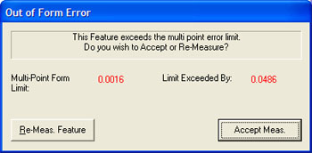 |
| figure 6, Form Test |
The order in which these two 3 point end groups are collected determines the
direction of the axis of the cylinder. After the data points have been captured, Geomet
will test the form error and if exceeded, will prompt you to < Accept > or
<
Re-Meas >, see figure 6.