Command Activation
| |
Tolerances→RunOut→Cylinder / Plane |
|
| Keyboard |
Main Menu |
Toolbar |
Introduction
Not all GeoTol functions are accessed through the GeoTol wizard. Some
special cases are separate functions such as the RunOut between and Plane
and Cylinder. The Cylinder / Plane RunOut routine is designed to calculate
the RunOut deviation of a Cylinder that is perpendicular to a plane at a
given radial distance. This calculation would be similar to placing a test
indicator on the end of a cylinder whose lateral position is fixed. The
indicator would be placed in a fixed position identified as the radial
distance. The part would be turned slowly and the Total Indicator Reading (TIR)
would be recorded, see figure 1.
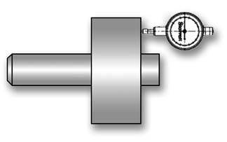 |
| figure
1, RunOut with Indicator Setup |
Setup for a RunOut
The first requirement to making this routine successful is to measure a
cylinder and plane with sufficient data points. Under these conditions the
cylinder and plane should be measured with at least 30 points, more if
necessary to locate a representation of the variances within the surface.
When performing the RunOut test manually, as shown in the example above,
you are actually capturing millions of data points while rotating the part.
The indicator will show a displacement from the highest to the lowest
reading. This spread will represent the RunOut.
A CMM, which builds features using discrete numbers of data points will
often never locate the total spread. The features are created using a
best-fit algorithm. The result will contain a small uncertainty between the
reported feature and the actual work piece. Therefore the higher the number
of data points used, the greater the chance you will return a RunOut that
resembles the manual method.
Determining the RunOut Value
Once you have completed measuring the Cylinder and Plane, activate the
RunOut routine, through the main drop down menus [Tolerances→RunOut→Cylinder/Plane].
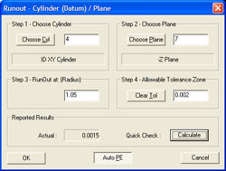
The RunOut tool will appear.
 |
 |
| Cylinder/Plane RunOut Tool |
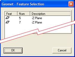
Feature Selection Tool |
Step 1 – Select Cylinder
Press the <Choose Cyl> button and the Feature Selector will appear with a
filter activated to show only Cylinders in your inspection report, see
figure Feature Selection Tool. Highlight the cylinder required for the RunOut routine and press
<Ok>.
Step 2 – Select Plane
Press the <Choose Plane> button and the Feature Selector will appear with
a filter activated to show only Planes. Highlight the plane required for the
RunOut routine and press
<Ok>.
Step 3 – Set the Radial Test Length
In this step, enter the radial distance from the axis of the cylinder you
would like the RunOut to be calculated at. This can be explained as the
location you would set the test indicator at.
Step 4 – Allowable Tolerance Zone
This RunOut tolerance value is the total allowable deviation of the
actual TIR value. If the calculated deviation exceeds this amount, it is
considered out-of-tolerance.
<Calculate>
The Calculate button updates the Actual: data field and is an optional
step before building the inspection step.
<Auto PE>
The <Auto PE> button is a push-on, Push-off button. When locked in the
down state, as shown in example on the previous page, Geomet will
automatically attach a Print Exception flag on the result when it attaches
the inspection step, see Print Exceptions for additional information.
<Ok>
To record the results in the inspection report, press the <Ok> button. An
entry will be made, see figure below.
 |
| RunOut Reported Results |
Adjusting the Tolerance Limit
 |
| Adjust Tolerance |
You can at any time adjust the maximum allowable tolerance limit. To
start, highlight the feature in the inspection report area and right-click
to activate the feature sub-menu. Choose Edit Tolerance from the list and
the Tolerance Dialog will appear, see figure. After making any necessary
changes, press the <Ok> button and the reported results will be updated.
|