Geomet home
DCC Settings, Junior, 101 & 301
Search tool Information index
 
       
7.01.337 Geomet Junior+, 101, 301
       
  Command Activation
 
  Introduction
 

The global settings for motion control speeds and basic distance settings are located within one tool called DCC Settings. Control values set by this tools are global settings that affect all motion behavior on program steps that do not contain an overriding attribute.

The control values are saved in the Geomet Systems Database and remain active even after a system restart.

The DCC Settings tool provide access to different control values depending on the type of CMM Interface that is installed on your CMM. The data entered is in Inches-per-second, or mm-per-second for speed values or the current unit of measure for all distance values unless otherwise noted.

NOTE: DCC Options works with Helmel designed PMAC DCC Coordinate Measuring Machines running Geomet Junior+, 101 or 301. For CMMs running running Geomet 501 with the Renishaw UCC controller, visit 501 DCC Settings.


Target Homing

Touch Point Speed Settings

Traverse Speed

The Traverse Speed is applied to motion between Interim Points (IP), Measurement Point (MP) and Stand Off Points (SO) in the following pairs; IP→IP, SO→IP, IP→SO and MP→SO. It does not apply to motion used to capture an MP or scanning operations.

The application of the Traverse speed by the motion controller is determined by the length of distance to travel and the application of motion blending.

The Traverse Speed is considered a maximum speed.

Probing Speed

The Probe Speed controls only one motion combination, the SO→MP. This control value should be used with caution. Speeds set to high will affect the accuracy of the data point as most probes are speed sensitive, see Tech Note #2.

It is suggested to use a setting of 0.250" or 6.35mm to provide consistent results. The Probe Speed is affected by other motion attribute settings such as the SO length and whether blending is active. The CMM requires a ramping time and distance when speed changes take place. Moving from a Traverse Speed of 15" per second to a Probe Speed of 0.25" per second will require a significant distance to transition. Should the SO length be small, such as 0.1", the CMM will not have sufficient distance to slow to the Probe Speed prior to making contact with the part. Care should be used when building your motion path to ensure conditions such as this example are minimized.

Interpolation Speed

This setting applies to CMMs that have newer Helmel/PMAC controller and may not be available on your CMM.

Interpolation Speed control one basic movement type; radial. This is utilized in RTP20 Probe Head articulation and some paths created by the Circle Generator. Interpolation Speed is similar to Travserse Speed as it does not affect the speed of the capture of a Measurement Point.

Coordinate System Selection

Touch Point Control Distances

Over Travel Distance (OT)

This OT control parameter determines how far past the MP the CMM will travel before it stops its motion. When you teach a motion path, the MP is captured or entered as a surface point on the inspected part. When the part is inspected under DCC control, the actual MP point may not be the same location as the programmed position. The part may be over or undersized.

The CMM will need to target the programmed MP position and travel past that targeted point to seek the actual MP position. It is common to use an OT value of 0.5" or 12mm.

Touch Point Control Distances
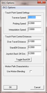
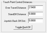
Stand Off Distance (SO)

The Stand Off Distance is used to calculate the position of the SO automatically during the teaching of a motion path. During the process of teaching, whether on the CMM or offline using motion generation tools, the process of capturing a MP will create an SO before and after the MP in the motion path.

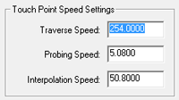
The Stand Off Distance should be set sufficient to allow the CMM time to transition from the Traverse Speed into the Probing Speed. In most cases this value could be set to 0.3" or 8mm. However, if the Traverse move is long such as 10" (254mm) or the Traverse Speed is high, transitioning into a short SO will not allow the inertia of the CMM structure to slow down and stabilize.

The SO position is calculated using the captured MP and the current direction to the last IP or SO. In the example shown at the right, the IP1 was recorded then the MP captured. Geomet will calculated the Pre and Post SO along the path from IP1 to MP and then inserted at the distance specified by the Stand Off Distance parameter.

There is a test that Geomet will perform prior to creating the SOs. Should the distance between IP1 and the MP be less than the distance specified the the Stand Off Distance parameter, the SOs will be created at the IP1 position. This ensures a tighter control when creating a motion path in areas of limited access on your inspection part.

Joystick Back off Distance

This parameter controls the back off distance the joystick will use when manually capturing an MP.

In most cases a value of 0.2" or 5mm is sufficient. However, conditions arise that these standard values will cause accidental contact during the retract as in a slot, small bore or other limited feature. Enter a new value into the control field and the motion controller will be updated with this value until changed.

Toggle BackOff Toggle Backoff Button

This button provides a quick switch between the current backoff distance and 0.020" (0.5mm). Pressing this will download the new value and close the DCC Settings tool.

Stand Off Distance

Motion Path Characteristics

Use Motion Blending

When Motion Blending is active, a blended radius move is executed between motion path move segments such as a IP→IP and a joining IP→SO segment. The motion controller calculates a smooth blended radius approximately 20% prior to the end of one segment into 20% of the next segment.

When this option is not checked, all motion path segments move to the exact start and stop position and pauses before moving into the next segment of the motion path. In limited areas this is the preferred setting.

When building the motion path, care should be taken to consider motion performance for the blending distance. For example do not create a motion path that moves around a corner to close to the part. The blending algorithm may begin the transition prior to clearing the corner and will cause a accidental probe trip.

A common example is driving a car. As you approach a corner your speed is adjusted downward to allow a smooth transition as you turn the corner. Should you approach the corner very fast, you will need to start your turn earlier to negotiate the turn safely. To control when the blending starts, add extra IPs along its path prior to reaching the corner.

Motion blending builds a smoother CMM performance and improves the inspection time.

Motion Path Characteristics

Show Motion Interface Data

The Data Interface is a direct connection to the CMM Interface. Each CMM Interface configures the Data Interface with unique tools specific to that CMM Interface needs.

Interface Strip

The Data Interface is located above the inspection report area shown on the Geomet screen. This tool is helpful when working with application engineers when looking at data directly from the CMM Interface. It has no inspection usefulness and may be disabled. 

Step and Repeat