|
Introduction
Geomet applies tolerance in either Linear and True Position, including RFS, MMC and LMC
when applicable. To understand the basics of tolerance, please refer to
Introduction to Tolerance in Geomet.
Activating the tolerance tool
To activate the tolerance tool directly from the report, highlight the Point feature
by left clicking on it. Activate the feature sub menu by right clicking and select the
[Edit Tolerance] command. To activate the tolerance tool using keyboard short
keys, press <Ctrl + t> which activates a dialog where the feature number is
entered, see figure 1. In either method, the appropriate tolerance dialog is
displayed with the current tolerance data displayed. For additional information see
Working with Geomet Tolerance
Windows.
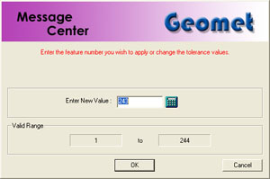 |
| figure 1, Enter Feature Number |
Tolerance of 1D Point features is limited to
Cartesian / Linear. Thus, 1D Points
only offer bilateral tolerance inputs, see figure 2.
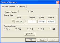 |
| figure 2, Tolerance 1D Points |
To apply tolerance nominal values, start by entering the nominal value in the column labeled "Nominal".
Enter the Plus and Minus values for
the bilateral tolerance band. Press the <Ok> button on the dialog or the
<Enter> key on the keyboard.
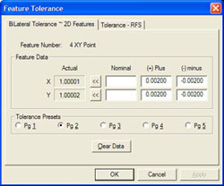
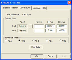
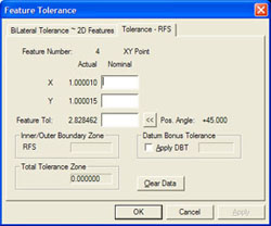
Tolerance of 2D Point features is possible in either Cartesian or Polar reporting
formats and in either Linear or RFS formats.
 |
 |
| figure 3, Cartesian format |
figure 4, Polar format |
|
|
 |
 |
| figure 5,
GDT Tolerance Cartesian Format |
figure 6, GDT Tolerance Polar
Format |
To activate the tolerance tool see
Working with Geomet Tolerance
Windows
In figure 3 an example of Cartesian format is shown. Figure 4 shows an example of the
Polar format and figure 5 and 6 shows the RFS Positional Tolerance format.
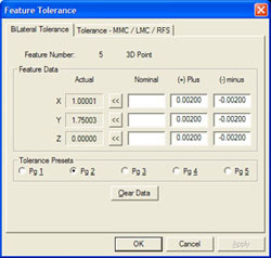
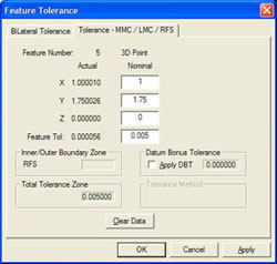
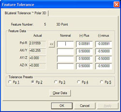
Tolerance of 3D Point features is possible in either Cartesian or Polar reporting
formats and in either Linear or RFS formats.
 |
 |
| figure 7, Cartesian format |
figure 8, RFS GDT format |
|
|
 |
| figure 9,
Polar Format |
To activate the tolerance tool see
Working with Geomet Tolerance
Windows
In figure 7 an example of Cartesian format is shown. Figure 9 shows an example of the
Polar format and figure 8 shows the RFS Positional Tolerance format.
Tolerance of Vector Point features is possible only in Cartesian
reporting formats. In addition to standard tolerance, Vector Points are
evaluated where they exist in a profile band that surrounds the inspection
piece.
 |
 |
| figure 10, Profile Band |
figure 11, Sub Menu |
To activate the tolerance tool see
Working with Geomet Tolerance
Windows, see figure 10. Here we show the standard tolerance dialog for
assigning values to the Nominal XYZ position, Profile
Band and Probe Deviation
plus/minus values.
When Vector Points were measured, the complete Tolerance
data was inserted as part of the reported feature. However, you may elect to
update the Tolerance data on one or more features.
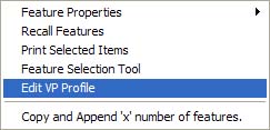
It is efficient to update the profile band limits on
multiple Vector Point features with just one operation. To accomplish this,
highlight all the Vector Point features in the report that share a common
profile band limit and right-click to activate the sub menu. Choose
[Edit VP Profile] and the standard "Vector Point Profile Band"
dialog will appear. You can then enter new plus/minus values for the Profile
Band and Probe Deviation. When accepted, all highlighted Vector Point
features will reflect the new values.
Since this method works on multiple Vector Point features,
the Nominal XYZ data fields will be protected and no changes can be made.
Related Procedures:
Points,
System Options,
Out-of-Tolerance Flash
Message
|