|
Introduction
Geomet offers many tools to assist in reverse engineering. These tools
include feature data point scanning and exporting measured features and data
clouds as IGES entities. Capturing data is handled by a wide variety of
common sensors from hard probes, electronic touch probes, analog scanning
probes to 3D laser scanning probes.
Reverse engineering is designed to provide a detailed explanation of an
artifact that may not have nominal data known about it. Identifying
prismatic features such as circles, planes, cones and other defined
geometric features combined with data clouds can then be exported into a
file format that a CAD system could read. The CAD system will then analyze
the information and form the solid objects or motion paths for CNC tools.
|
Summary
of Reverse Engineering Tools: |
|
Select Scan Method |
Chooses
the active Scanning Mode within Geomet. |
|
GeoTracer |
Hard Probe drag scanning used on manual
CMMs. |
|
Touch Probe Data Clouds |
Capturing of discreet data point clouds
utilizing manual or DCC CMMs. |
|
Line Scan |
Single line capturing of data points
under DCC control. The motion path adjusts to perform surface following. |
|
Radius Path Auto Scan |
Radial path capturing of data points
under DCC control. This is designed to work on ends of cylinders where the path must
follow a rim. This tool does not perform a contour following during motion. |
|
4 Point Boundary Surface
Scan |
Creates a flexible 4 corner boundary
that rows and columns of data points will be captured within. Exclusion zones can be
defined to eliminate areas that data points should not be captured such as holes or other
obstacles. The captured data points conform to a accurate row/column pattern designed for
accurate surface fitting. This tool perform contour following. |
|
Radial Boundary Surface
Scan |
Radial boundary scan is similar to the 4
point boundary scan but uses a diametric border that the rows and columns will be
contained. |
|
Cardinal
Spline Generation |
A cardinal spline is a series of
individual curves between points joined to form a larger curve. The spline is specified by
an array of points and a tension parameter. A cardinal spline passes smoothly through each
point in the array; there are no sharp corners and no abrupt changes in the tightness of
the curve. By passing through every point, there are no missed points that can cause
errors when fitting a surface over the splines. |
|
Exporting IGES Entities |
Export tool used to create a IGES file
for use to exchange data with a CAD system,
see
Supported IGES Entities. |
Reverse Engineering for Surface Generations
The capturing of data points over an unknown surface utilizing a
Coordinate Measuring Machine produces a data point cloud of XYZ values.
The values represent the ball center of the stylus attached to the CMM.
Touch probes are triggered devices that do not provide information as to
the location where on the stylus ball the actual touch of the surface
occurred.
Therefore, utilizing the data cloud in reverse engineering requires
that the CAD system must perform an offset surface command before the
final solid is created. To assist the CAD system, Geomet offers
controlled data point collection tools and the exporting of fitted B-Spline
Curves through the data points.
Data clouds produced by the 4-Point and Radial Boundary Scan Tools are
built on a Row and Column structure that is aligned with the Machine
Coordinate System. As shown below in the left example, we are looking
directly over the data cloud that was taken on a sphere. The rows and
columns are consistent and aligned with the X and Y-axes of the CMMs natural
movement. The example on the right shows the same data cloud rotated to show
the Z-axis height.
 |
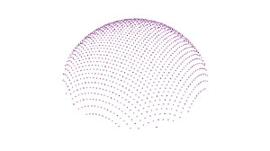 |
| Viewed from +Z |
Viewed from +X, -Y, +Z |
Another example is a close-up of the fan blade shown in Radial and
4-Point Boundary Scans. When viewed from +Z, the rows and columns are again
uniform.
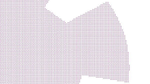 |
| Fan Blade as viewed from +Z |
The result of building uniform rows and columns allow for simple building
of splines and surfaces when imported into CAD system.
|